
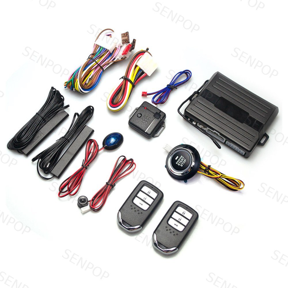
The central-locking trigger type decides everything about the install — and it takes ten minutes with a multimeter to identify, before a single wire is cut. Skip the check and the result is a kit that locks one door, locks all the doors the wrong way, or quietly damages the vehicle's own lock control module.
This article is the expanded version of one section in our kit-selection guide: the trigger type. It gives you a three-step identification procedure, a clear stop-signal for single-wire systems, and the diode rule for merging door triggers. It is written for the installer doing the work — and for the importer who wants to brief them properly.
Why the Trigger Type Decides Everything
Aftermarket keyless and alarm systems do not drive the door-lock motors directly. They send a short pulse into the vehicle's own central-locking circuit, and the vehicle does the work. That pulse is either a negative pulse (a brief connection to ground), a positive pulse (a brief connection to 12V), or — on some vehicles — something the aftermarket kit cannot produce at all.
Feed a negative-trigger circuit a positive pulse and the current runs backwards through parts that were never designed for it. Sometimes the symptom is immediate: locks cycling the wrong direction, a blown fuse. Sometimes it is delayed and expensive: a damaged factory lock-control module, billed to whoever held the screwdriver.
What our systems support, stated plainly: the 8803 series is documented to support both positive-trigger and the common negative-trigger central locking — that is one of the reasons its vehicle coverage is wide. The 8807 documents a negative-trigger output. What our documentation does not cover is single-wire (resistance-based) locking — see the stop-signal below. And always confirm against the manual for the exact model and version in the box, not against this article alone.
Three Types and How to Tell Them Apart
| Type | How the vehicle switches its locks | What the meter shows | Aftermarket connection |
|---|---|---|---|
| Negative trigger | A switch momentarily connects the lock-control line to ground | Resting: 12V on the line. Operating: drops toward 0V | Kit's negative-lock wires tap the line |
| Positive trigger | A switch momentarily feeds the lock-control line 12V | Resting: 0V (ground) on the line. Operating: rises to 12V | Kit's positive-lock wires tap the line |
| Single-wire / resistance-based | One line carries both directions as changing resistance or voltage levels; often no separate lock/unlock wires exist | Ambiguous — a single line whose value shifts between states, no clean 12V-to-0V swing | Not a direct connect. Stop — see below |
The first two are mirror images, and the multimeter tells you which mirror you are looking at in one operating cycle. The third is not a mirror image of anything — it is a different architecture, and it is the reason this article exists.
The Multimeter Test, Step by Step
Setup
- Multimeter set to DC voltage, 20V range or auto.
- Black probe on a clean chassis ground point — unpainted metal, not a painted bolt.
- Vehicle doors unlocked, key out, everything off. Work on the driver's door lock switch wiring first; it is the reference every other door is compared to.
- Backprobe the connector where possible rather than piercing insulation — a pierced wire is a future corrosion fault.
Step 1 — read the resting voltage
Probe the lock-control line with the system at rest. Near 12V: you are likely on a negative-trigger line (it rests high, pulses low). Near 0V: likely positive-trigger (rests low, pulses high). Somewhere in between, or nothing sensible: do not guess — you may be on a data line, and data lines punish probing.
Step 2 — watch it change
Hold the probes steady and have an assistant operate the lock switch through one lock/unlock cycle, slowly. You are watching for a clean swing: 12V falling toward 0V (negative trigger, lock direction), or 0V rising to 12V (positive trigger). Note which direction of switch movement produces which swing — that pairing is the whole answer, and writing it down takes ten seconds and prevents the ten-minute reversal later.
Step 3 — check the other doors
Repeat on one more door. Here is the trap the industry documentation has warned about for decades: many vehicles do not share one common door-trigger line across all doors. The driver's door may rest high while the passenger doors rest low, or the doors may not share a line at all. If the doors do not agree, the door-trigger inputs need to be merged with isolation diodes — see the section below — and the lock-trigger answer from step 2 still stands for the locking circuit itself.
Two cautions that apply throughout: this article deliberately names no vehicle-specific wire colours — colours vary by market and model year, and a colour remembered from another car is a false friend. And on any vehicle where the meter shows something this procedure does not describe, stop and photograph it — send us the reading and the vehicle, not a guess.
Single-Wire Systems: Stop and Re-Plan
The single-wire (resistance-based) system is the one that cannot be wired directly — not because the pulse is the wrong polarity, but because there is no pair of lock/unlock lines to receive pulses at all. The vehicle's own module watches one line and interprets resistance or voltage levels: one state means lock, another means unlock, a third may mean something else again. Injecting a pulse into that line does not command the locks; it lies to a module that is listening carefully, and modules remember insults.
Making these vehicles work requires an interface that translates — typically a relay arrangement or a dedicated module that reads the kit's outputs and emulates the resistance states the vehicle expects. That is a per-vehicle engineering decision, not a wiring shortcut.
The stop-signal, stated plainly: if your meter shows a single ambiguous line instead of a clean resting-then-swinging pair, do not connect the kit. Our product documentation covers negative- and positive-trigger vehicles; it does not document single-wire interfaces, and we will not pretend it does. Re-plan: either fit a proper interface module with the vehicle's documentation in hand, or choose a different installation approach for that car. A kit sold is recoverable; a factory lock module damaged is not.
Merging Door Triggers with Diodes
When Step 3 shows the doors do not share a common trigger line, the standard remedy is to merge them through isolation diodes — one per door line, so each door can pull the input but the doors cannot feed each other (without isolation, opening one door can falsely trigger the circuit through another door's switch path).
The principle in one paragraph: the diode conducts only in one direction, so each door line can drive the shared input while being shielded from the other door lines. What we will not do in this article is name diode part numbers, ratings or orientation for your vehicle — diode direction is unforgiving, a reversed diode in the wrong circuit can damage the kit or the vehicle module, and the correct specification belongs to the kit manual and the vehicle documentation, not to a generic article. Use the wiring diagram supplied with your kit; if the doors still disagree after a diode-merged install, photograph the setup and send it to us with the vehicle details before energising it again.
Long-standing industry references — installer databases and major alarm manufacturers' installation manuals alike — treat the diode-merged door trigger as a standard procedure, which is exactly why the shortcut version of it on a forum is so dangerous: the procedure is real, but its parameters are vehicle-specific.
Frequently Asked Questions
Does the 8803 support both trigger polarities?
Yes — the 8803 series is documented to support positive-trigger central locking as well as the common negative trigger, which is part of its wide vehicle coverage. The 8807 documents a negative-trigger output. Confirm the exact version's manual before install; version differences matter.
What happens if I connect the wrong polarity?
Best case: locks cycle the wrong way or a fuse blows immediately. Worst case: the factory lock-control module is damaged — a delayed, expensive failure that appears days after the installation was signed off. This is why the ten-minute meter test precedes every install.
Can I install on a single-wire system with just relays?
Not directly. Single-wire systems need an interface that emulates the resistance or voltage states the vehicle's module expects — a relay arrangement or dedicated module, designed against that vehicle's documentation. Our product documentation does not cover single-wire vehicles, so treat them as a re-plan, not a wiring variation.
Why do my door triggers disagree between doors?
Many vehicles have no common door-trigger line — the driver's door is often on its own circuit. The standard remedy is merging the door lines through isolation diodes so they share one input without feeding each other. Follow the diode specification in your kit's manual; direction and rating are not generic.
The meter shows a voltage the procedure doesn't mention. What now?
Stop. You may be on a data line or a circuit this article does not describe. Do not connect the kit, do not ground the line to "test" it. Photograph the reading and the connector, note the vehicle, and send it to us — we will tell you whether the model supports that architecture or whether the vehicle needs a different plan.
Not sure which type the vehicle is?
Send us the meter readings from the three steps — or a photo of the door-lock switch connector — and we will tell you whether the model supports that vehicle directly, needs an interface, or needs a different plan.
Ask before you cut →Related Reading
- How to Choose a Push Button Start Kit — the selection criteria this article expands on
- Push Button Lit but Engine Won't Crank: 7 Checks — when the symptom appears after the install
- 8803 PKE Keyless Entry System — both trigger polarities documented
- All PKE Keyless Entry Systems — the full line