
Scope: this guide is written specifically for the 9002 RFID push button start system (DC 12V) and follows that unit's installation documentation. Wire colours, the 6P function assignment and the arming/alarm behaviour are model-specific — do not apply them directly to other push start models including the 24V S9001X.
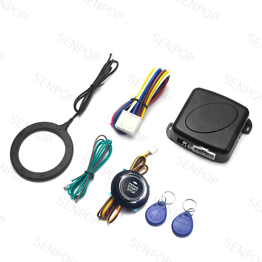
Installing an RFID push button start system with a hidden immobilizer is very doable for a trained installer — but only if the wires are located correctly and the factory transponder chip is handled properly. This guide walks through the complete installation of a 9002-type system: how the system behaves day to day, how to relocate the original transponder chip, how to find and connect each wire on the 6P start-function harness, and how to troubleshoot the connections that most often go wrong.
Safety Notes Before You Start
This procedure involves the vehicle's ignition system and anti-theft components. Disconnect the battery before wiring, work with the vehicle secured, and have the installation carried out by a qualified auto-electrician. The steps below follow the supplier's installation documentation for the 9002; always verify colours and procedures against the official manual supplied with the actual unit before connecting anything.
How the System Operates Day to Day
Understanding normal behaviour first makes faults much easier to diagnose later:
If the system does not behave this way after installation, the sections below cover the connections that cause almost all of the deviations.
Original Transponder Chip Handling & Installation
Vehicles with a factory transponder immobilizer need the original chip to stay within range of the engine's immobilizer antenna — otherwise the engine cranks but never fires. The solution is to relocate the chip together with the sensing ring taken from the key lock cylinder:
- Step 1: Remove the transponder chip from the original remote key — usually a small rectangular black body, as shown on the right of the illustration below.
- Step 2: Remove the sensing (immobilizer antenna) ring from the original key lock cylinder, as shown.
- Step 3: Tape the removed chip and the lock cylinder's sensing ring together with fabric (cloth) tape, as shown.
- Step 4: Install the combined ring and chip assembly inside the dashboard and secure it with cable ties.
Alternative simple installation: the chip can also be attached directly to the sensing ring at the key lock cylinder position.
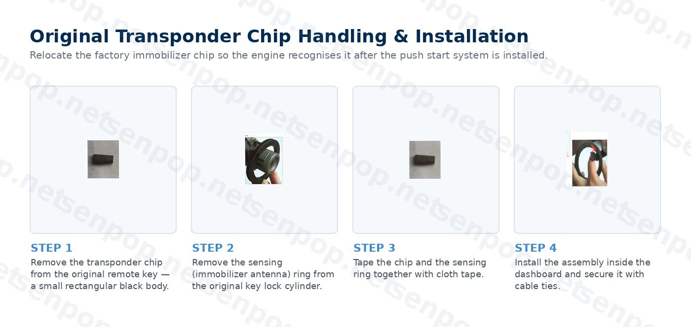
Hiding the combined assembly inside the dashboard — rather than leaving it at the lock cylinder — is what gives the hidden-immobilizer effect: without the ID card, the car cannot be started even if the wiring is tampered with.
Locating the 6P Start-Function Wires
All wire colours below refer to the main unit's harness. Work through them in this order and test each connection before moving on:
- Power wire — main unit red power wire. Disconnect the original car key, then test the thick wires on the large connector behind the key lock cylinder for constant 12V — usually one or two. Connect one thicker constant-12V wire to the main unit's red power wire. If there are two, join them together and connect them to the red power wire to increase power capacity.
- ACC wire — main unit blue wire. Insert the original key and turn it to the first (ACC) position, then test the remaining thick wires (excluding the power wire). Typically one wire is live at ACC; connect it to the main unit's blue wire. If there are two or more such wires, join them together and connect them to the blue wire.
- ON wires — main unit white wire (ON1) and brown wire (ON2). Turn the key to the second (ON) position and test the remaining thick wires (excluding power and ACC). Generally two wires are live at ON. Then crank the engine with the key and test both ON wires during cranking: the wire that stays live throughout cranking is ON1 — connect it to the white wire; the wire that cuts out momentarily and then recovers is ON2 — connect it to the brown wire. Note: if neither ON wire cuts out during cranking, join the white and brown wires together, join the vehicle's two ON wires together, and connect the two pairs so the vehicle can start normally.
- Starter wire — main unit yellow wire. Crank the engine with the original key and test the remaining thick wires (excluding power, ACC and ON). A wire live only during cranking and dead once the engine has started is the starter wire — connect it to the yellow starter wire (a few vehicle models use ACC-cut starting and are exceptions). Note: if two starter wires are found, join them together and connect them to the yellow starter wire.
- Ground wire — main unit black wire. Connect the black ground wire to a steering-column bolt on the left side and tighten firmly.
- Foot-brake wire — main unit orange wire (positive trigger). Find the brake wire that is live when the pedal is pressed and connect it to the orange brake wire. If this wire is not connected or is connected incorrectly, the one-button start function will not operate — only ACC and ON power will be available.
Wiring Q&A: the Four Connections Installers Ask About
Handbrake detection wire
This wire enables the remote start function; without it there is no remote start. For manual-transmission vehicles, for safety, the handbrake detection wire must be connected and the handbrake engaged before remote starting. If the wire is very difficult to locate, or the vehicle has no handbrake signal, the detection wire may be grounded directly — provided the vehicle is never left in gear when parked with the engine off. For automatic-transmission vehicles the detection wire can be grounded directly. It leaves the factory set to negative trigger, so the vehicle's handbrake signal must be negative (grounded) when engaged; if the signal is positive, a relay must be added to convert it to negative trigger. Note: on a few models the handbrake signal is +12V triggered — connect a diode in series (anode to the vehicle's handbrake wire, cathode to the handbrake switch) and join it to the main unit's handbrake wire.
Blue ACC output power wire
This wire powers the vehicle's audio system; if it is not connected or connected incorrectly, the audio cannot be turned on. To locate it: insert the original key, turn it to the ACC position and test the wire behind the lock cylinder — the live wire there is the ACC output power wire; join it to the main unit's blue wire. Note: on this main unit the ACC output is cut during cranking, which suits most models. If the vehicle's ACC wire stays live during cranking, also connect the vehicle's ACC wire to the white ON1 wire.
White and brown ON output power wires
These two wires power the instrument panel (also called flameout wires). If they are wrong or missing, the instrument panel will not light up or the vehicle will not start. The white ON1 wire powers the whole vehicle and does not cut out during cranking; the brown ON2 wire powers loads such as the air conditioning and headlights and may cut out during cranking to leave enough current for the starter motor, then restores power after start. To locate: turn the key to ON and test the wires behind the lock cylinder; then crank and test both — the one that stays live is ON1 (white wire), the one that cuts out momentarily is ON2 (brown wire). Notes: if both ON wires stay live during cranking, join white and brown together and join the vehicle's two ON wires together, then connect the pairs. If a model has three ON wires, connect all that stay live during cranking to the white wire, and those that cut out to the brown wire.
Yellow starter output wire
Connect it to the wire behind the lock cylinder that is live momentarily while the key cranks the engine. Some models have two such wires — join them together with the main unit's yellow wire. If this wire is not connected or connected incorrectly, the starter motor will not crank and the vehicle will not start.
Troubleshooting Common Symptoms
Symptoms map directly to the connections above. Check them in this order, and stop and consult a professional (or the supplier) if a measurement does not match the description — do not improvise on ignition circuits:
- Push button starts nothing, only ACC/ON works. The foot-brake wire is not connected or is connected to the wrong wire — re-check the orange wire connection (Step 6).
- Starter motor never cranks. The yellow starter wire is missing its connection, or the wrong wire was chosen — repeat the Step 4 test during actual cranking.
- Instrument panel dead or vehicle will not start after wiring. ON1/ON2 are swapped or not joined per the cranking test — redo Step 3, paying attention to which wire cuts out during cranking.
- Audio does not turn on. The blue ACC output wire is not connected — see the ACC Q&A above.
- Remote start does not work. The handbrake detection wire is not connected or the vehicle's handbrake signal polarity does not match — see the handbrake Q&A above.
- Vehicle cranks but will not fire on a transponder-equipped car. The original chip was not relocated with the sensing ring, or the assembly sits out of range — redo the chip handling steps.
Installation content © SENPOP, adapted from the supplier's installation documentation for the 9002 product family. Always verify wire colours and procedures against the official manual supplied with the unit.
Frequently Asked Questions
What should I check before installing this type of system?
Confirm the vehicle is DC 12V (this system does not support 24V), check whether the car has a factory transponder immobilizer (chip relocation required), identify the central locking and ignition wiring behind the lock cylinder, and read the official manual for the specific unit before connecting anything.
Can this system be installed on any car?
It targets 12V vehicles and is designed to work on cars with no remote or alarm, cars with an existing aftermarket alarm, and cars already fitted with a PKE system. Compatibility still depends on each vehicle's ignition wiring — confirm the specific vehicle with the supplier before ordering.
Is a push button start system the same as a PKE keyless entry system?
No. A push button start system replaces the key turn with a start button (and, on this model, adds a hidden immobilizer). A PKE system adds passive keyless entry — the car unlocks as the driver approaches. The two are often combined in one kit, but they are different functions; see our article PKE vs RKE for the full comparison.
What if a wire colour on my vehicle does not match the guide?
Stop. The procedures above identify wires by testing their behaviour (constant 12V, ACC-live, ON-live, cut during cranking), not by trusting the vehicle's insulation colour. If a measurement does not match the description, stop and consult a qualified installer or ask the supplier before connecting.
Need the official manual or sourcing for this system?
Browse the SENPOP 9002 product page for confirmed specifications and kit contents, or request the technical data sheet for any model.
Request a Quote